Bonetti Rubinetterie Valduggia S.r.l.
![]()
BRV is active on the international market from 1970 as an established manufacturer of components for heating systems and hydronic. The range of products is vide and it sweeps over the basic components such as ball valves and pipe fittings, thermostatic radiator valves, up to the more complex products of the ModvlvS range, that comply with the new requirements of integration of the renewable energy, in standard heating installations.
The products are in continuous development and they stand out for the well known BRV quality level. Moreover customer service and training are an added value and a point of strength of BRV.
![]()
WE REGULATE AND SUPPLY CLEAN ENERGY
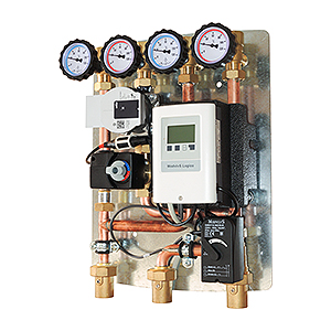
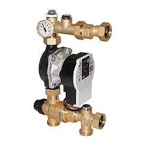
Made for standard heating systems, solar thermal and renewable energy heating systems, the ModvlvS range of products offers always an up-to-date solution and an easy installation, with a special care for the design. A wide selection of fittings and accessories allows to rely on BRV for any need of carrying out an installation. ModvlvS pump units, all pre-wired, couple up-to-date climatic controllers with high efficiency electronic circulating pumps, so offering an optimal balance between comfort, safety and energy saving.
STANDARD PRODUCTS
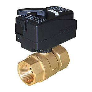
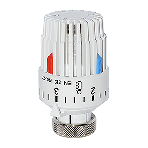
The range of BRV standard products stands for quality and excellent long life. The whole production process exploits all the experience and the know-how used in the production of more complex products. The wide offer of products fulfils all the installation needs, even with products aimed at special apllications.
Among these products we point out the range of thermostatic radiator valves “Thermostar”, the special patented security device “Sigilblock” and the special “Checkball” non return valves.
CUSTOM MADE
From the very beginning BRV has been active and innovative: our mission has always been the complete customer satisfaction. Within the last 10 yers we devoted ourselves hard to the development of custom made products and to make them we have invested in new machinery and in highly flexible production processes; this allowed BRV to work in direct contact with the customers to project and realize custom made products. Thanks to our higly qualified staff we can make a working prototype in less than one week, starting from the initial 3D design.